Tutorial: Building a Robot
Overview
This is a brief tutorial on how to build a robot that meets the 2026 Weaponized Plastic rules. The tutorial walks through the components used, and why they were selected. A full Bill of Materials (BOM) is available at the end of the tutorial for convenience.
Drive Motors and Wheels
Our basic robot, like most fighting robots, is going to use differential drive. This configuration uses two drive motors - when the motors are moving in the same direction at the same speed, the robot will go forward or backwards in a straight line. When the two motors are moving at different speeds or in different directions, the robot will turn.
Many of the robots we built last year used very cheap (~$10) 20mm diameter gear motors. These were an unmitigated disaster - almost every one had a gearbox failure, with many of them literally exploding into dozens of pieces.
The Max Brushed - Beetleweight planetary gearmotors from Repeat Robotics were a significant step up for reliability. For our differential drive robot, we will need two of these motors, at a cost of $30 each.
There are numerous options for wheels. Some competitors prefer soft foam aircraft wheels, but our tutorial robot will use a harder design from BaneBots. These wheels may not have as much traction as the softer foam wheels, but they will last a long time. The BaneBots Wheels also need a BaneBots Hub. Since our motor has a 6mm shaft, that is the hub size we need.
NOTE: the wheels come in a variety of colors, which indicate the durometer (how hard the robot is). You can feel free to select a different color, we’ve merely linked the softest, grippiest version here.
Weapon Drive
One of the challenges of building a 1Kg fighting robot is the overall weight budget. Heavier weapon motors will spin up faster and impact your opponent more powerfully, but the required components to build a functional robot already consume a good portion of the weight budget.
Last year we had good success with a number of different weapon designs all using the same 27mm diameter brushless motor. These come in a variety of different speeds, denoted by a higher “KV” value. For this tutorial we are using an 1800KV speed motor.
Our tutorial robot uses a horizontal spinner, which we will design in the 3D Printed Parts section below.
Battery and Charger
There are numerous very-cheap batteries out there. They can easily explode. So we’re going to recommend a name brand battery with some built-in added protections to avoid overdischarge, etc. Be sure to fully read the manual that comes with any battery or charger!
Spektrum batteries have some built-in intelligence, but require a Spektrum-branded charger. Our tutorial bot uses an 11.1V battery to take full advantage of our drive motors, but some robots may choose to use lower voltage 7.4V batteries. The 2200mAh rating tells us how much energy the battery contains when fully charged. Higher numbers provide longer runtime and the 2200mAh battery should basically last all day. Some competitors have had good success with smaller 1300mAh batteries, which should be more than enough for several matches, and saves on weight when compared with larger batteries.
NOTE: Spektrum batteries come with several different sizes of connector - be sure to get the IC3 connector version. The smaller IC2 connector is a pain to deal with.
You’ll also need a matching pigtail to connect the robot to the battery, and a power switch. Both components are called out in the BOM below. The power switch we use allows the robot to be turned on and off with a 3/32” hex driver, meaning that we can’t accidently hit the switch and be turned off during a match.
The Spektrum S100 charger is an inexpensive way to charge your battery. It uses a USB-C connector and many of you will already have a high wattage USB-C power supply from a laptop or tablet - if not, this is still the cheapest smart charger even with the added cost of a USB-C power supply.
Radios and Electronics
We’ll need three pieces of electronics to control our robot:
- Electronic Speed Controller (ESC) for the drive motors.
- Electronic Speed Controller (ESC) for the weapon motor.
- Radio with receiver to command the robot.
While you could use two separate motor controllers for the drive motors, it is preferable to use a dual motor controller that mixes the two channels together. This tutorial uses the Repeat Robotics Dominion Dual ESC, but we also had good results with the slightly lower cost $17 FPVKing controller at the 2025 competition.
The weapon motor is brushless, and so it requires a brushless motor controller. This inexpensive one works well with the chosen weapon motor.
As long as your drive motor ESC can handle the mixing of the two motor channels like our recommended one, you only need a very basic transmitter radio. The FLYSKY FS-i6x is a very inexpensive option that was well tested at our 2025 event.
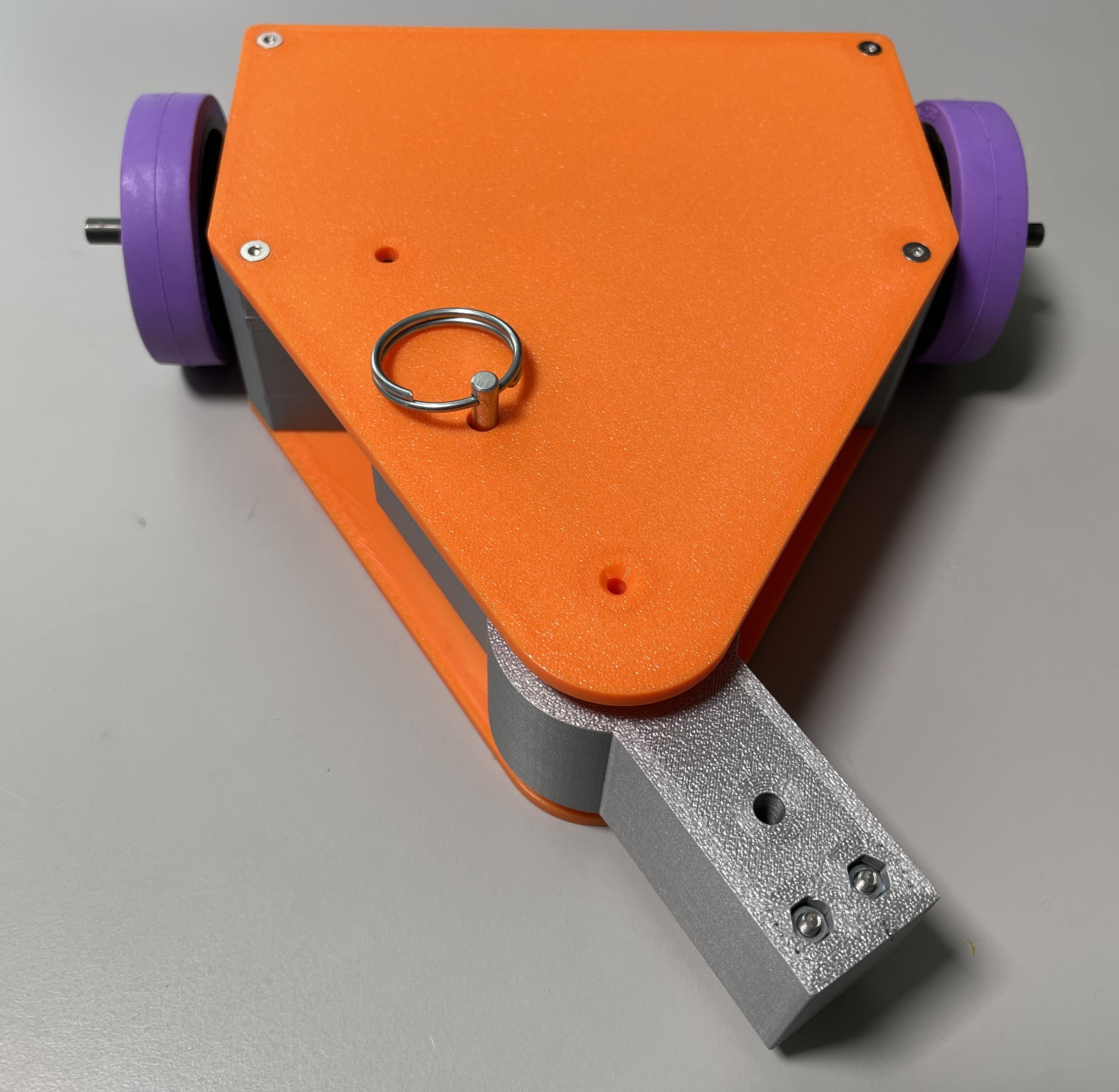
3D Printed Parts
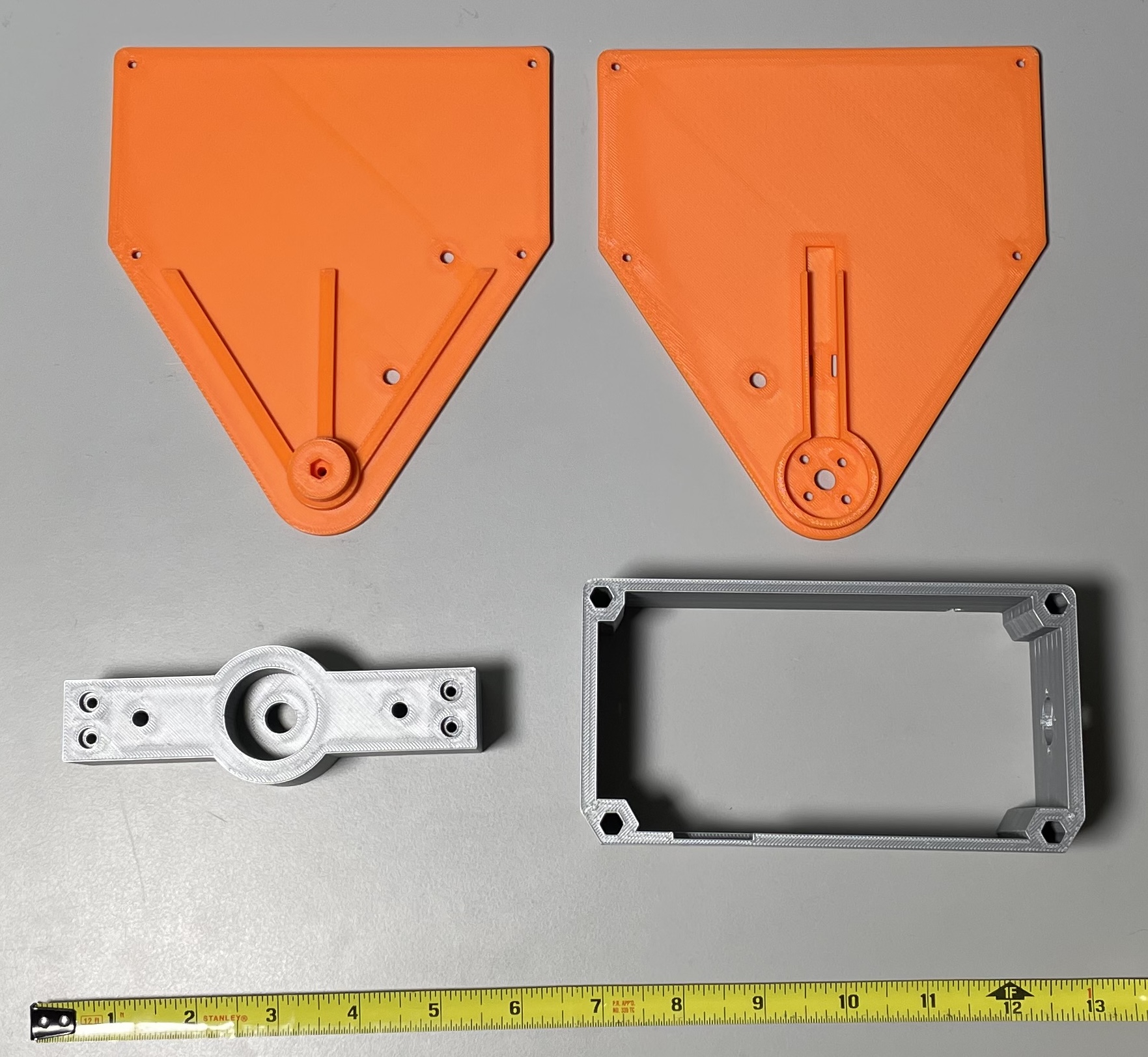
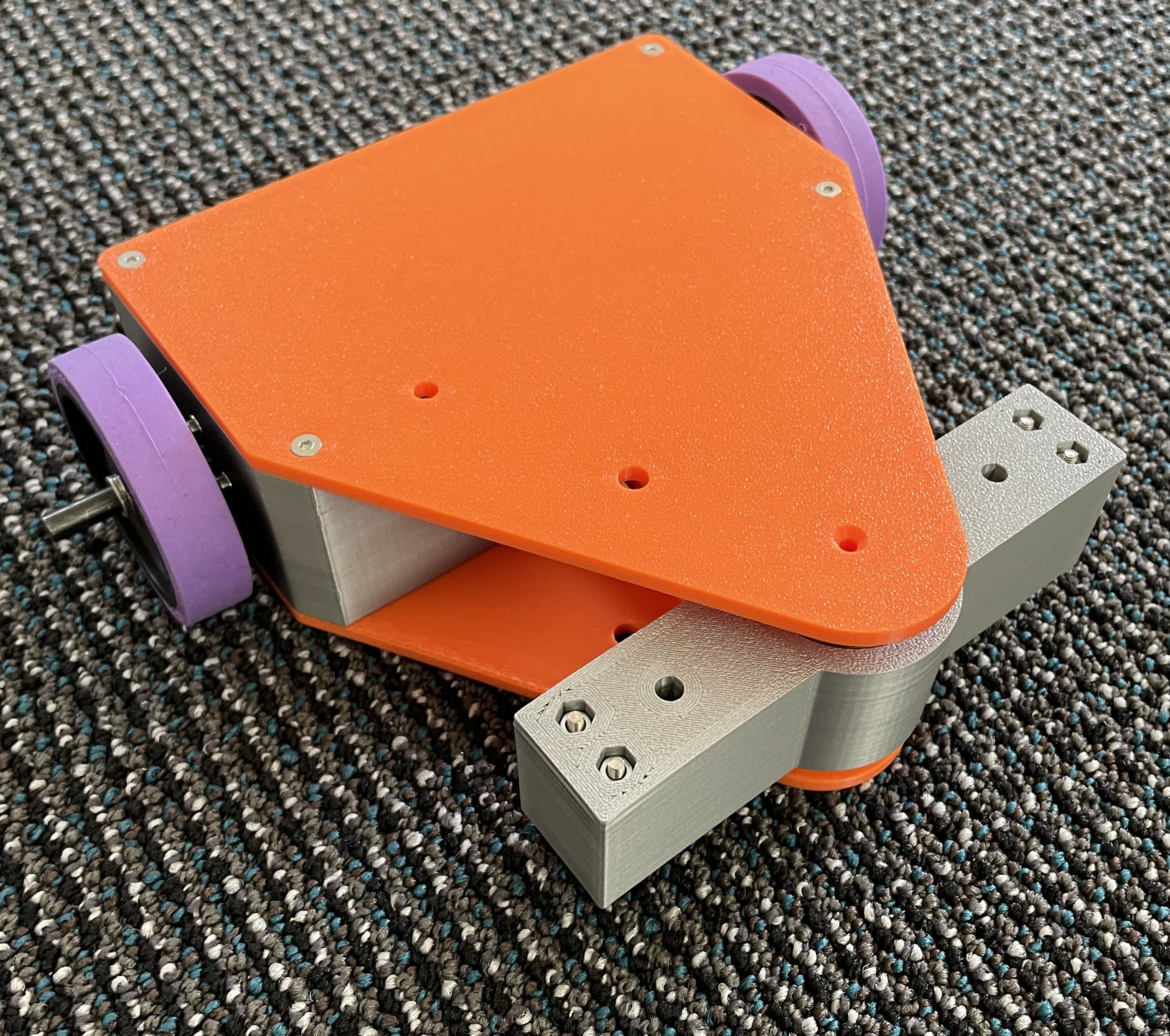
The mechanical design of the robot has the following features:
- Limited amount of expensive hardware and fasteners.
- Easy to assemble and repair. The top and bottom plates sandwich all the components together with a few standoffs. These standoffs also act as a clamshell of sorts which reduces the risk of the 3D printed parts delaminating along the layer lines.
- Symmetric body - you can still drive when inverted (although the actual control will be all backwards to the operator).
- The weapon is mounted directly to the motor, avoiding the need for belts, pulleys and any tensioning mechanism. The downside is that the motor will take more of the brunt of impacts. Similar to the body, the weapon has a set of screws that hold the layers together. To meet the rules, these screws need to be set back from the cutting edge of the weapon.
When printing the robot body and weapon, we want to use the highest infill possible, while staying under the weight limit. On my Bambu X1C, I used the following settings:
- Body: Standard with 3 walls
- Top, Bottom and Weapon: Strength profile
There are some options here for customizing the robot - you can print the robot in different colors, the weapon shape can easily be adjusted. The robot as designed is currently around 850g, so there is significant headroom for denser prints, bigger weapons, etc.
Part files:
Hardware, Tools, etc
Several tools will be required to build the robot:
- Soldering iron for assembling the electronics
- Wire cutter/stripper
- 1/16” hex driver for wheel assembly
- 3/32” hex driver for power switch
- 1.5mm hex driver for M2 screws
- 2.0mm hex driver for M3 screws
Bill of Materials
The items below will require four separate orders from Repeat Robotics, Banebots, Amazon and McMaster.
| QTY | Description | Cost (ea.) |
|---|---|---|
| 2 | Repeat Robotics Max Brushed Motors | $30.00 |
| 1 | Repeat Robotics Dominion Dual ESC | $27.50 |
| 1 | Fingertech Switch | $9.00 |
| 1 | Power Distribution Board | $6.00 for QTY5 |
| QTY | Description | Cost (ea.) |
|---|---|---|
| 2 | Banebots T61, 2-3/8” Wheels | $3.30 |
| 2 | Banebots T61, 6mm Shaft Hub | $4.20 |
| QTY | Description | Cost (ea.) |
|---|---|---|
| 1 | FEICHAO A2212 - 1800KV | $12.99 |
| 1 | Brushless ESC for Weapon Motor | $16.99 |
| 1 | FLYSKY FS-i6x | $54.99 |
| 1 | Spektrum 11.1V 2200mAh Smart Lipo | $34.99 |
| 1 | Spektrum S100 1x100W USB-C Smart Charger | $32.99 |
| 1 | Spektrum IC3 Pigtail | $10.99 |
| 1 | 6804 20x32x7mm Bearing | $9.99 for QTY5 |
| 1 | LED 12V, 6mm Hole | $9.49 for QTY10 |
| 1 | Kapton Tape (20mm) | $5.99 |
| 1 | 22AWG wire, 10ft ea of black and red | $5.18 |
For the hardware below, from McMaster, most of the parts are sold in quantities of 50 or 100. The QTY column refers to how many actual screws you will need from the 50 or 100 you order.
| QTY | Description | Cost (ea.) | Where Used |
|---|---|---|---|
| 2 | M2 Hex Nut | $2.22 for QTY100 | Power switch |
| 10 | M2 Washer | $1.78 for QTY100 | Power switch (2) and motors (8) |
| 10 | M2 x 10mm SHCS | $6.97 for QTY100 | Power switch (2) and motors (8) |
| 5 | M3 Hex Nut | $2.81 for QTY100 | Top plate (1) and weapon (4) |
| 4 | M3 x 30mm SHCS | $5.18 for QTY50 | Weapon |
| 4 | M3 x 6mm FHCS | $6.85 for QTY100 | Attaching weapon motor to bottom plate |
| 9 | M3 x 12mm FHCS | $6.19 for QTY100 | Body standoffs (8) and top plate (1) |
| 4 | M3 x 45mm Standoff | $1.49 each | Attaching top/bottom to body |
| 1 | Ring Grip Quick Release Pin | $1.90 each | Safety pin to lock weapon |
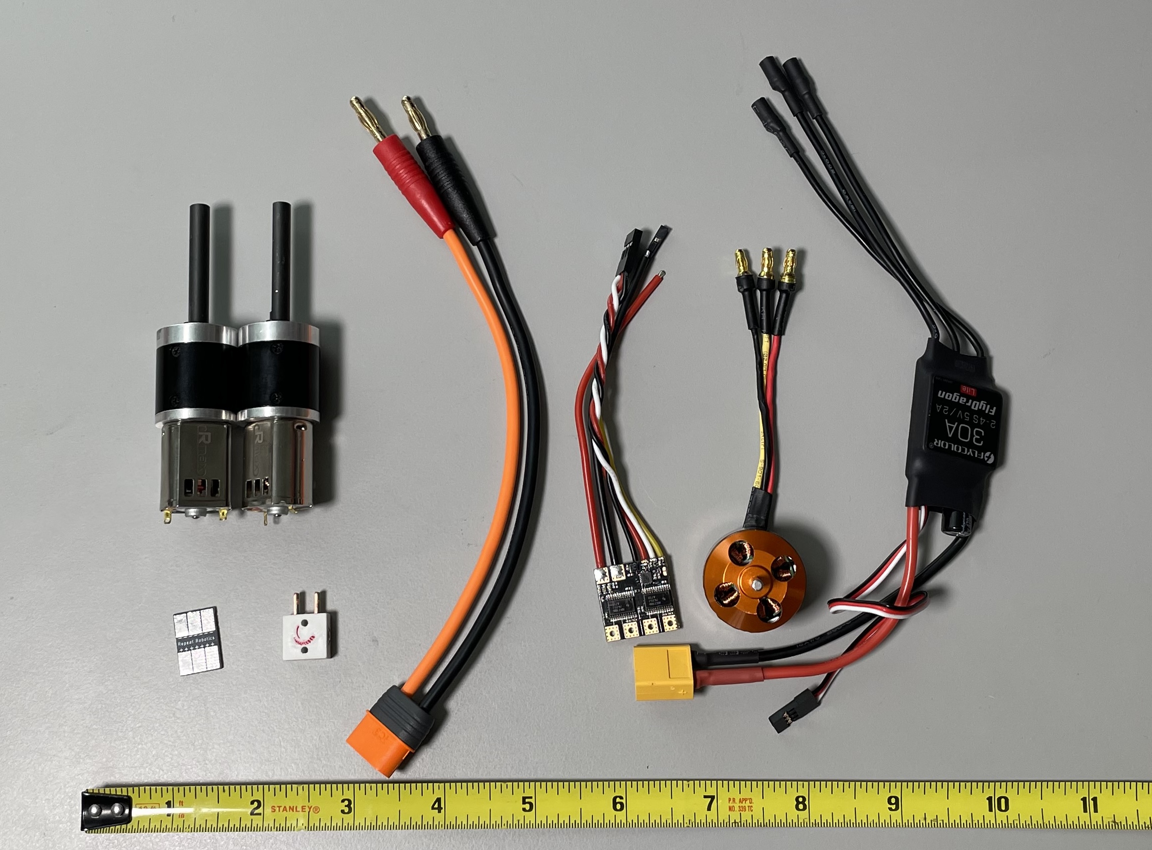
1. Solder Battery Pigtail
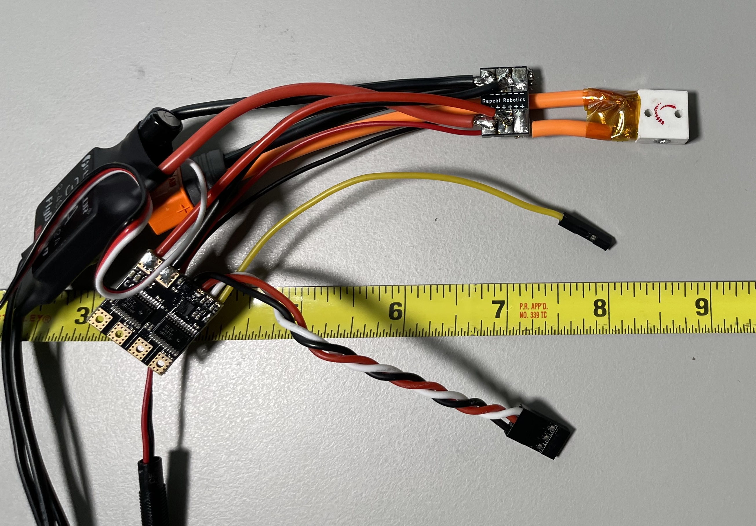
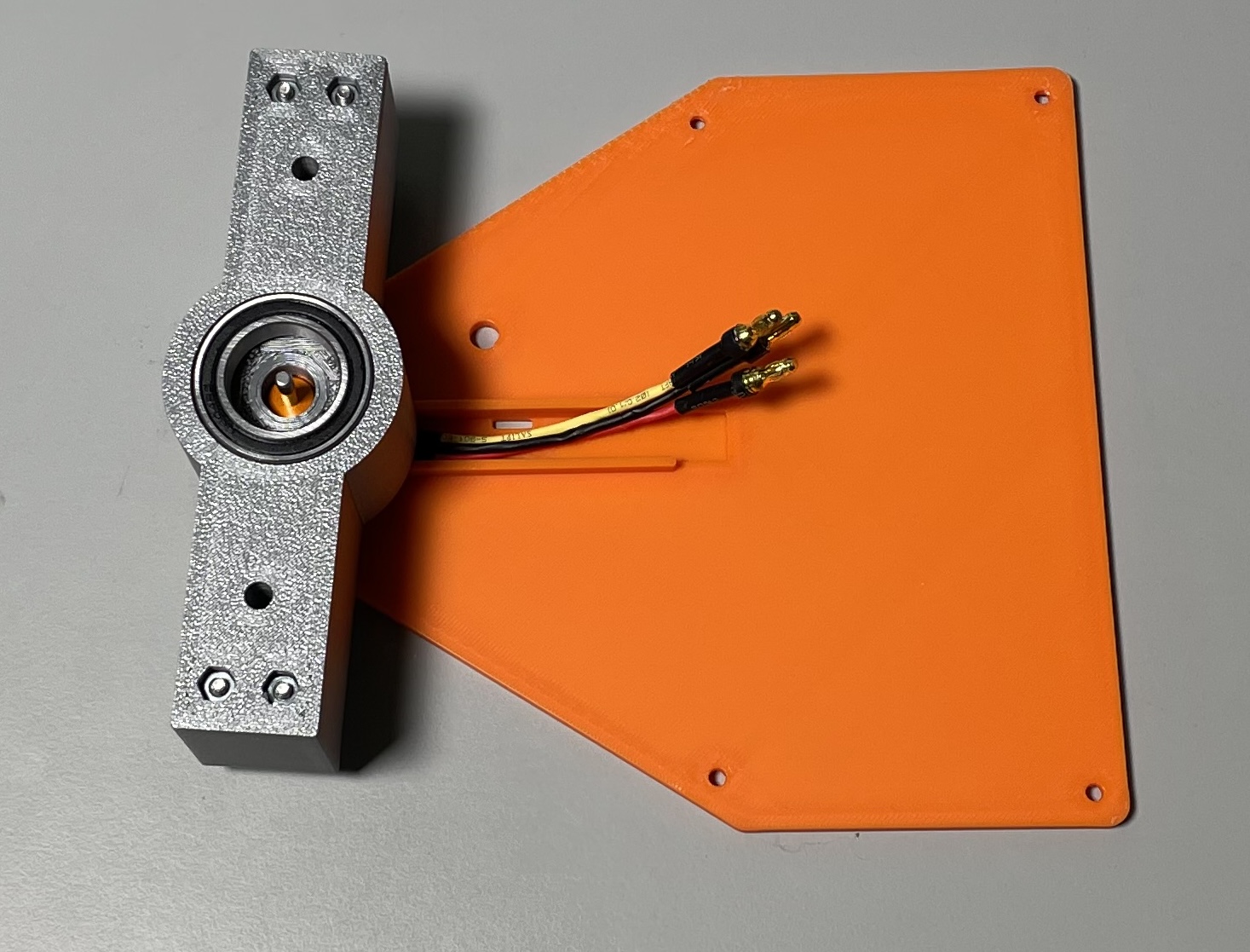
First, gather the electronics components:
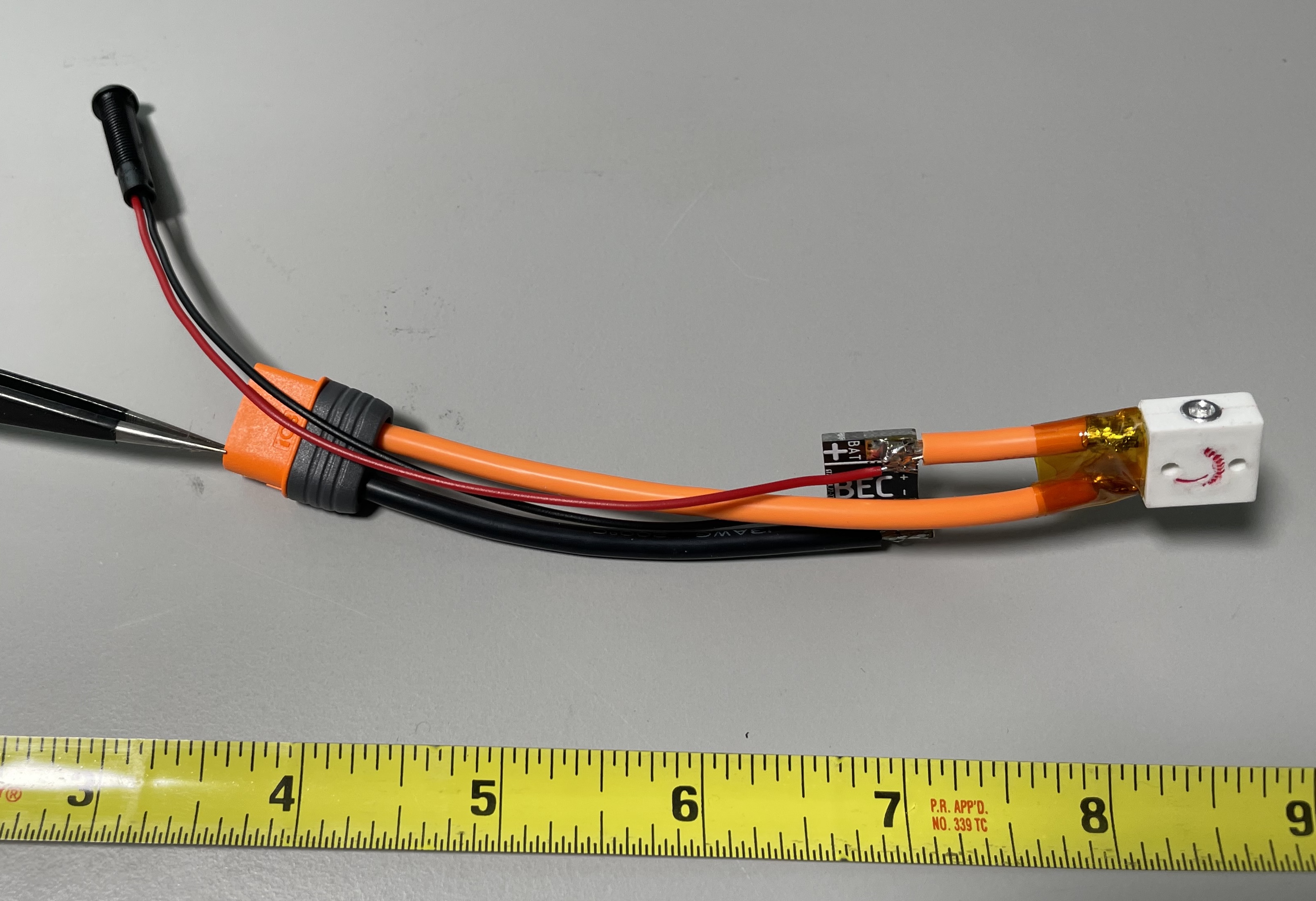
Now, we will connect the hot side of the battery pigtail to the power switch.
- Trim off a short (~1.25”) piece of the hot (orange) cable and use it to connect the power switch to the BAT+ connection on the power distribution board
- Solder the remaining hot side of the battery pigtail to the other terminal of the power switch.
- Protect the leads on the power switch with some Kapton tape.
- Connect the ground side of the battery pigtail to the BAT- connection on the power distribution board.
- Connect the power LED to the smaller BAT+/- terminals on the power distribution board.
Your assembly should look like below:
2. Solder Motor Controllers
Now we can connect both motor controllers to the power distribution board. Cut the yellow connector off the brushless motor controller and solder to the appropriate pads on the back side of the power distribution board. Solder the dual motor controller power leads to the power distribution board.
You can then wrap the power distribution board in some Kapton tape to protect it from shorting out.
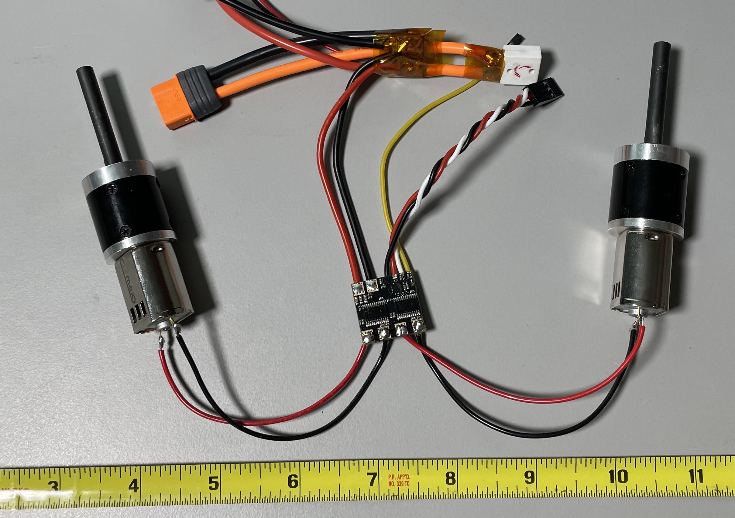
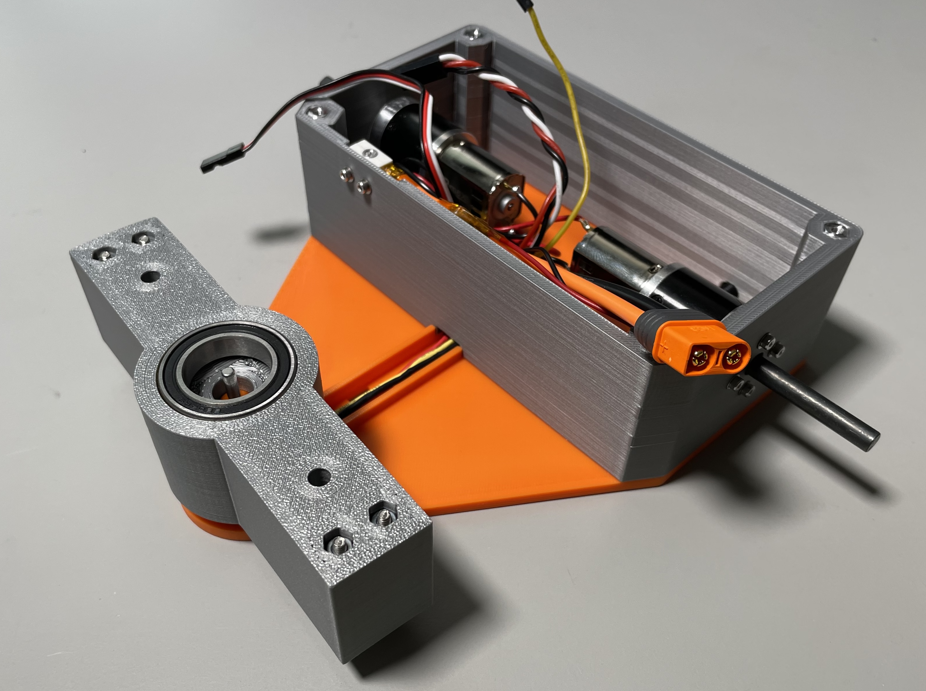
3. Solder Motors
Using short leads of 22AWG wire, attach the motors to the dual motor controller. Be sure that the red wires connect to the red terminals on the motors, and that the order of red and black on the dual motor controller matches the image below:
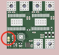
We also need to solder the jumper on the motor controller in order to enable mixing:
Finally, wrap the motor controller with Kapton tape to prevent shorts.
4. Assemble Weapon
Install the bearing and weapon motor into the into the plastic weapon part. The fit is adjusted by wrapping tape around the motor or bearing. The fit for each part should be snug.
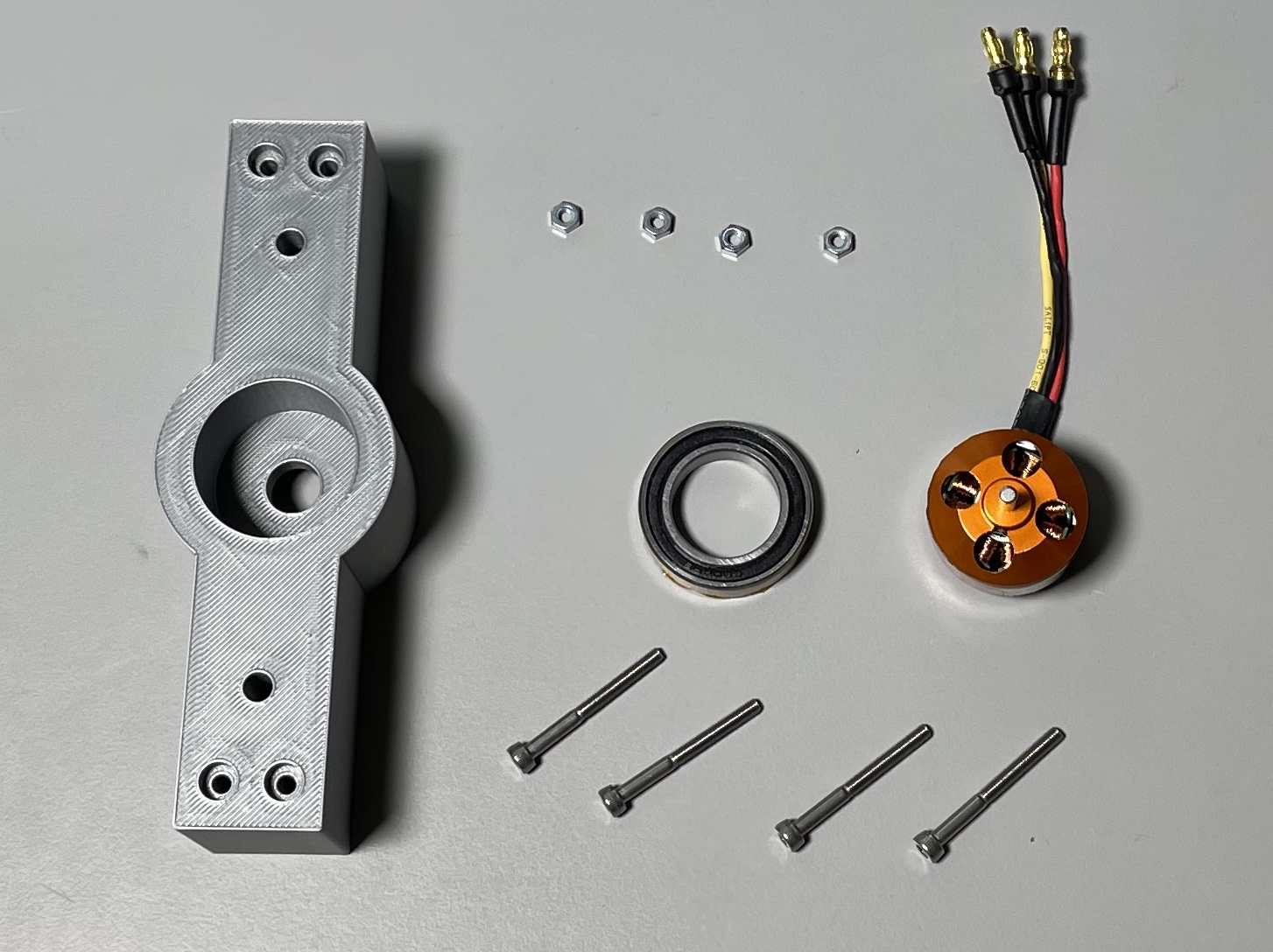
Strengthen the weapon by installing (4) M3x30mm Socket Head Cap Screws (SHCS) and (4) M3 nuts into the exterior edge of the weapon body. Attach the weapon motor to the bottom plate using (4) M3x6mm Flat Head Cap Screws (FHCS).
OPTIONAL: cutting the small shaft off the top of the weapon motor will allow you to install a screw and hex nut into the top plate of the robot directly over the motor. This can improve the reliability of the weapon as it prevents the layers of the top plate from separating where they mesh with the bearing.
5. Install Drive Motors
Install each of the motors into the body using (4) M2 x 10mm SHCS and (4) M2 washers each. The motor connected to the “A” set of terminals on the motor controller will be your LEFT side motors.
Install the power LED in the back wall of the body by sliding the cables through the slot and then pulling the LED into position.
The body can then be attached to the base using (4) standoffs and (4) M3x12mm FHCS. The power switch can be attached to the body using (2) M2 x 10mm SHCS and (2) M2 nuts.
OPTIONAL: you may want to cut the drive motor shafts down as they are a bit long. If you don’t have access to a hacksaw they will just stick out past the wheels - this is fine.
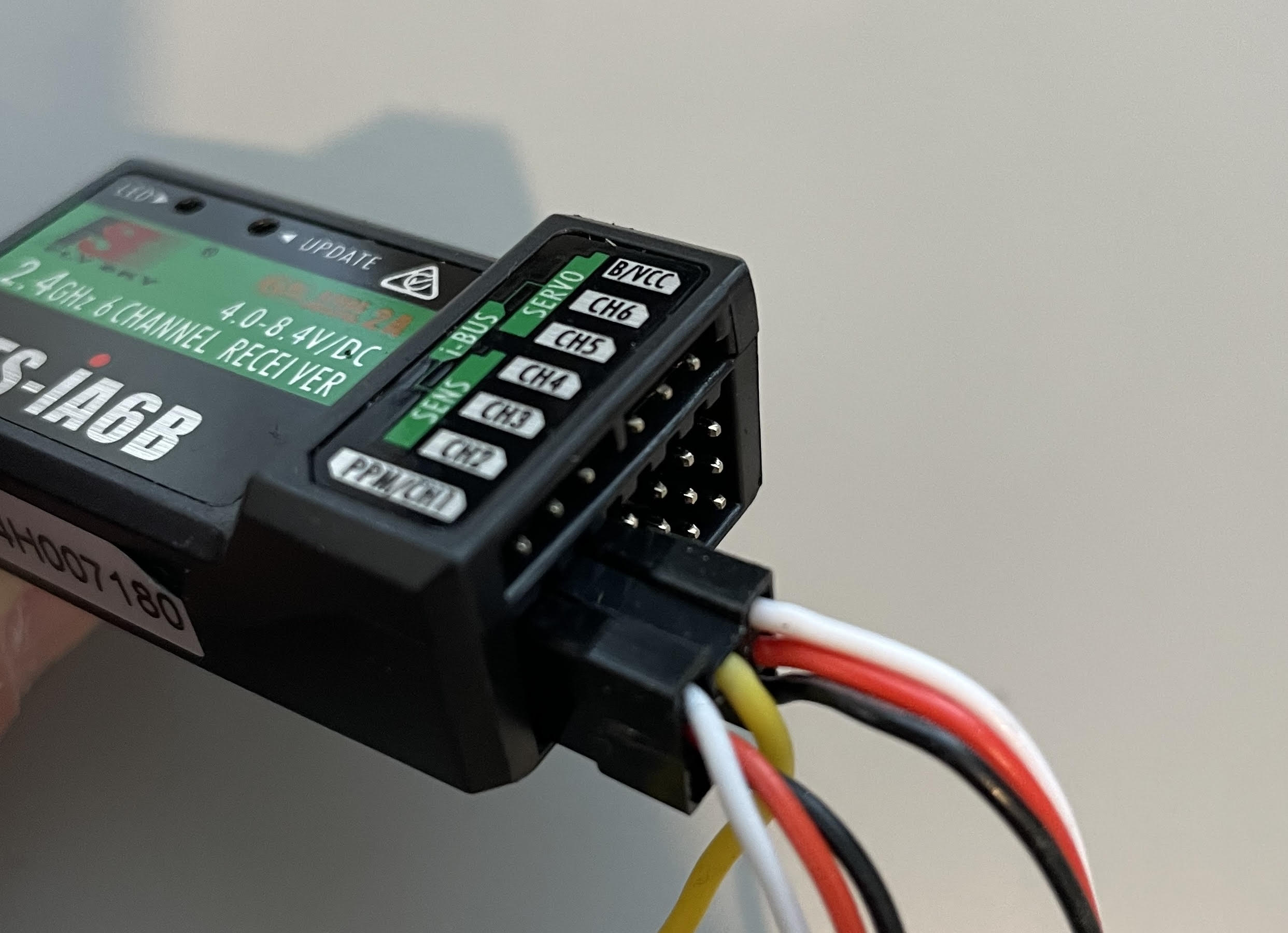
6. Connect Receiver Electronics
The channels are:
- Dual motor controller - WHITE signal
- Dual motor controller - YELLOW signal
- Weapon motor controller
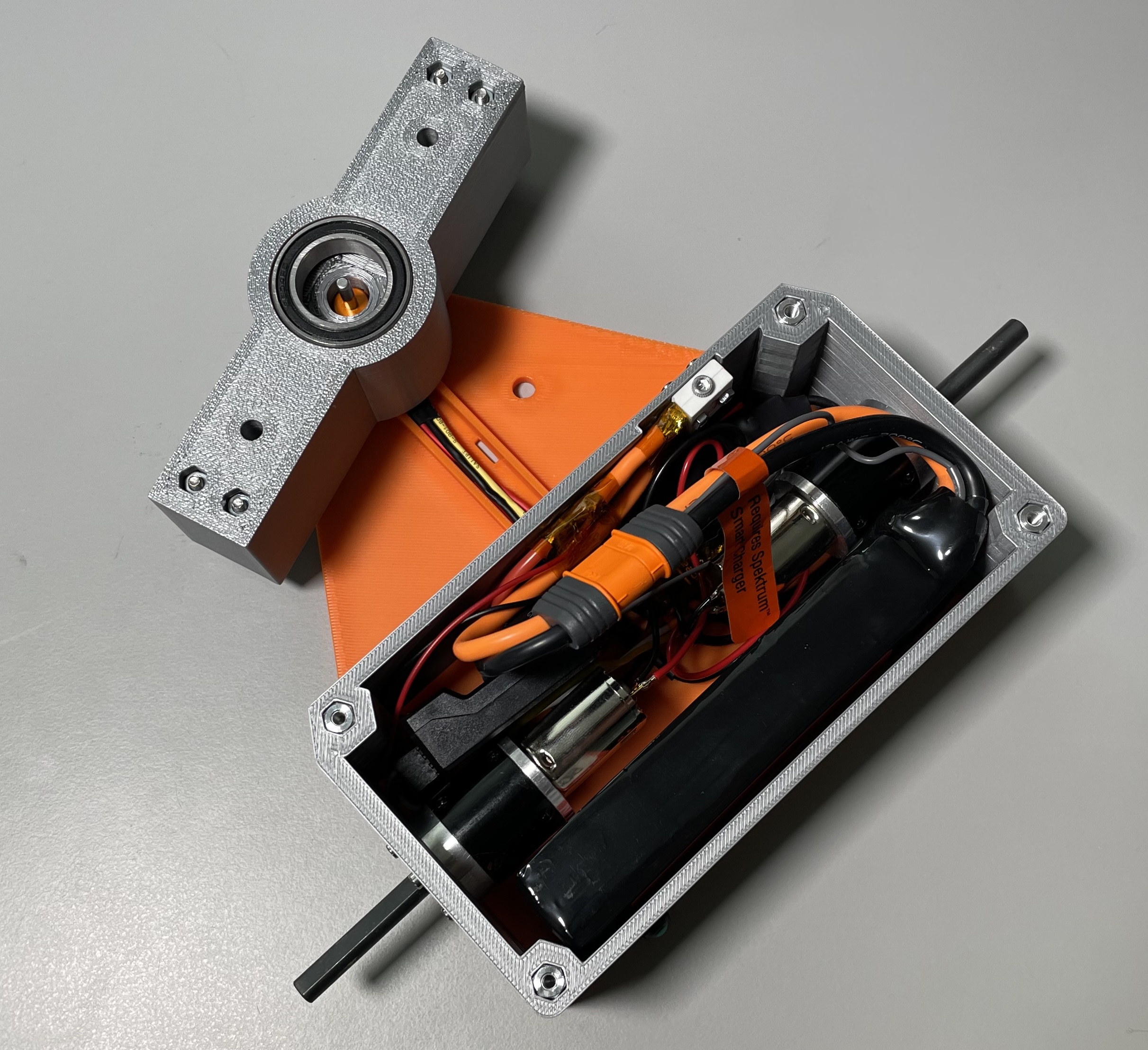
7. Final Assembly
Ensure that the power switch is OFF and then connect the battery and close up the clamshell. Secure the top plate with (4) M3x12mm FHCS.
Be sure to install the safety pin through the top plate into the weapon whenever the robot is outside of the arena!
Always move the weapon throttle (left joystick) to the lowest position before powering anything on.
8. Setup Radio
With the safety pin installed and the robot turned ON, we will setup the radio.
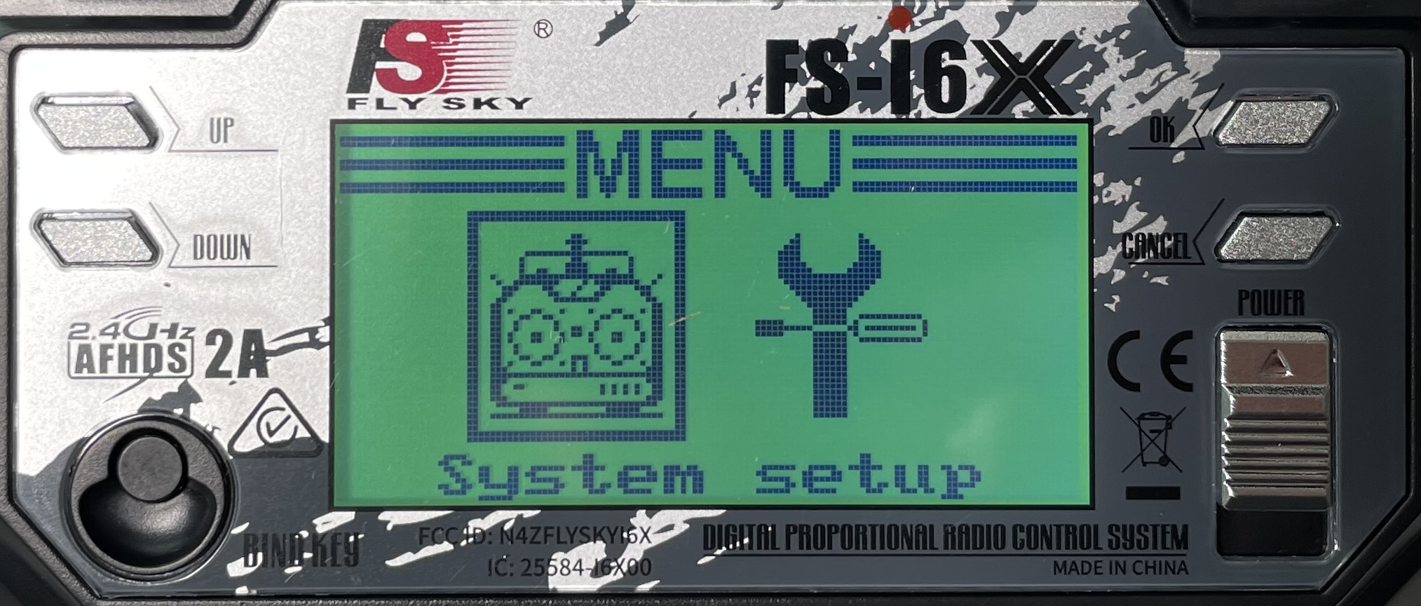
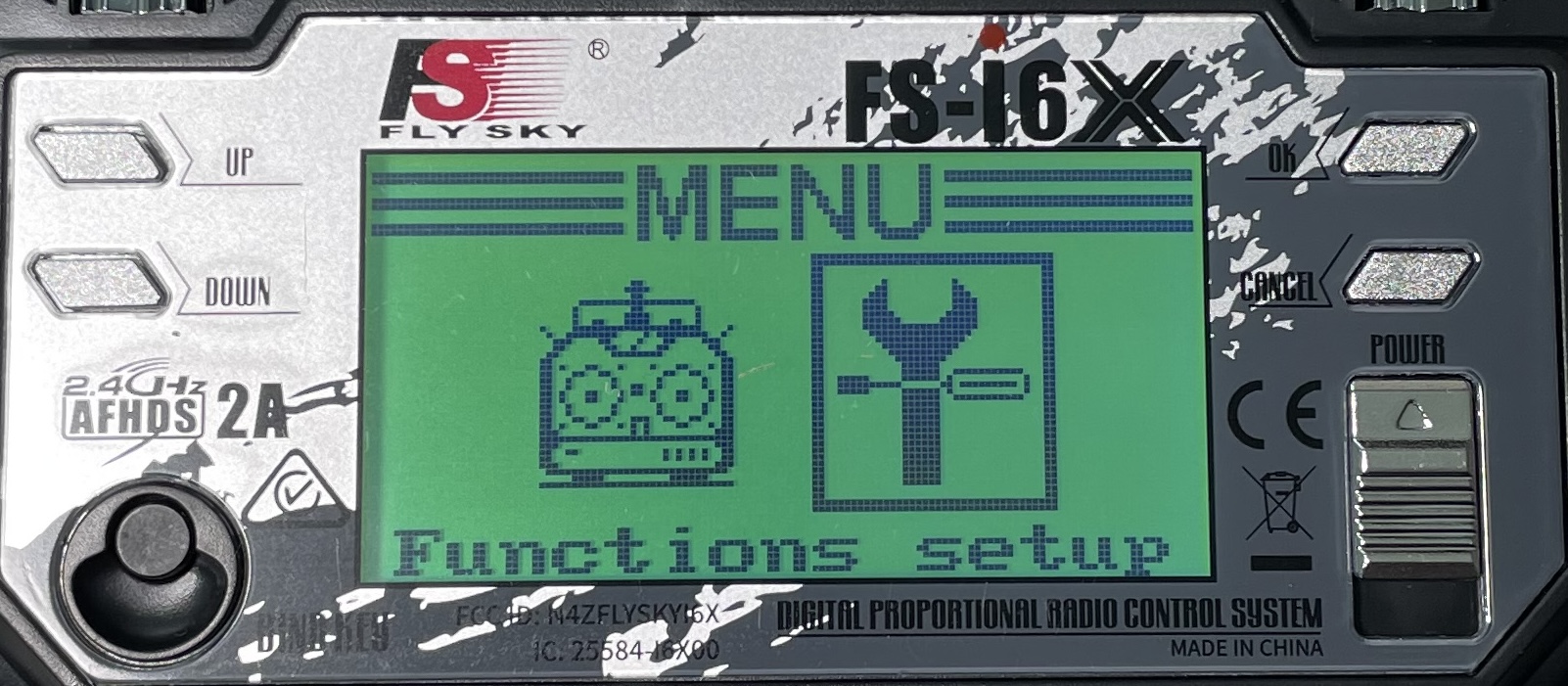
First, we need to make sure that if our radio turns off unexpectedly, or loses signal, that our robot returns to a safe state. To do that, hold down the OK button to enter the menu, shown below:
From the menu screen, press OK again to enter “System Setup” screen:
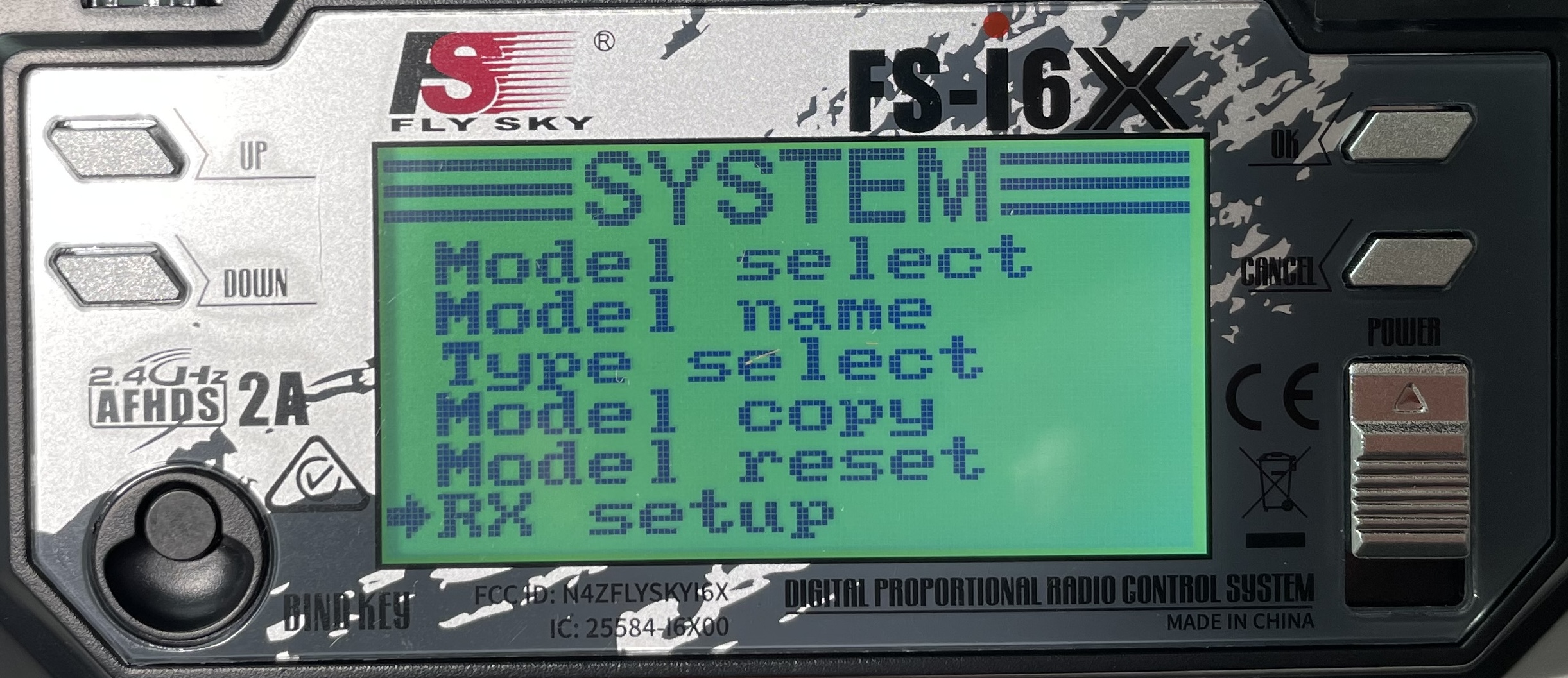
Scroll DOWN to select “RX Setup” and press OK, this will bring up the “RX Setup” screen:
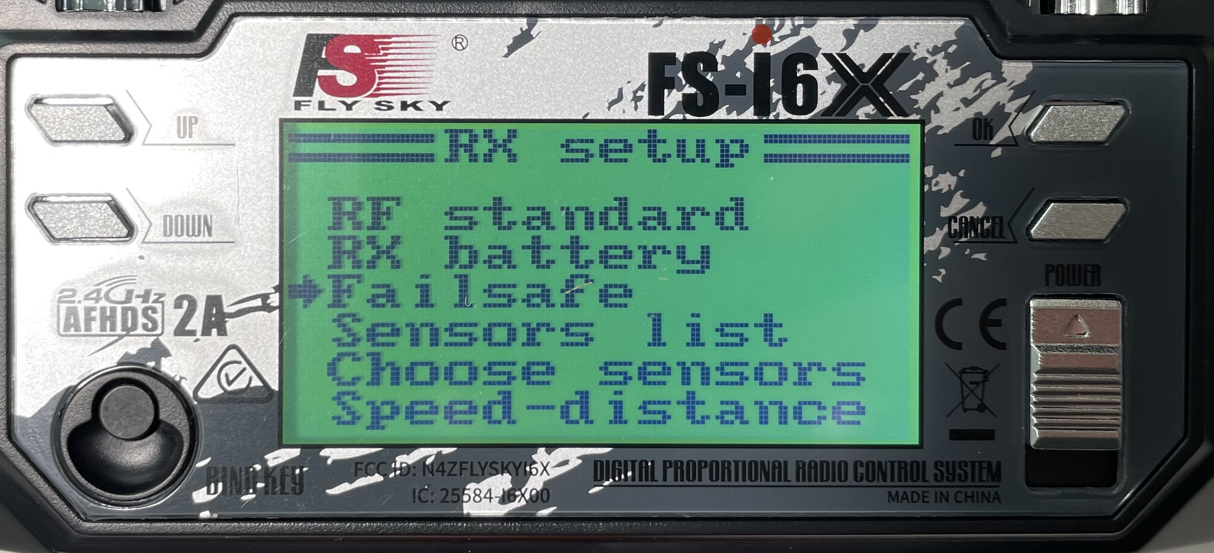
Scroll DOWN to select “Failsafe” and press OK:
In this “Failsafe” screen, we wan to enable Channel 1 and 2 with a setting of 0% - this will stop the robot drive motors. We need to set Channel 3 to as close to -100% as possible to turn off the weapon motor.
For each of the channels, you will press OK to enter the settings for that channel, then use UP or DOWN to change the setting from OFF to a number. Make sure the sticks aren’t being touched and that the weapon throttle (left joystick) is in the DOWN position. To save the setting hold the CANCEL button until the menu changes (a quick press will discard the change, you need to HOLD the button).
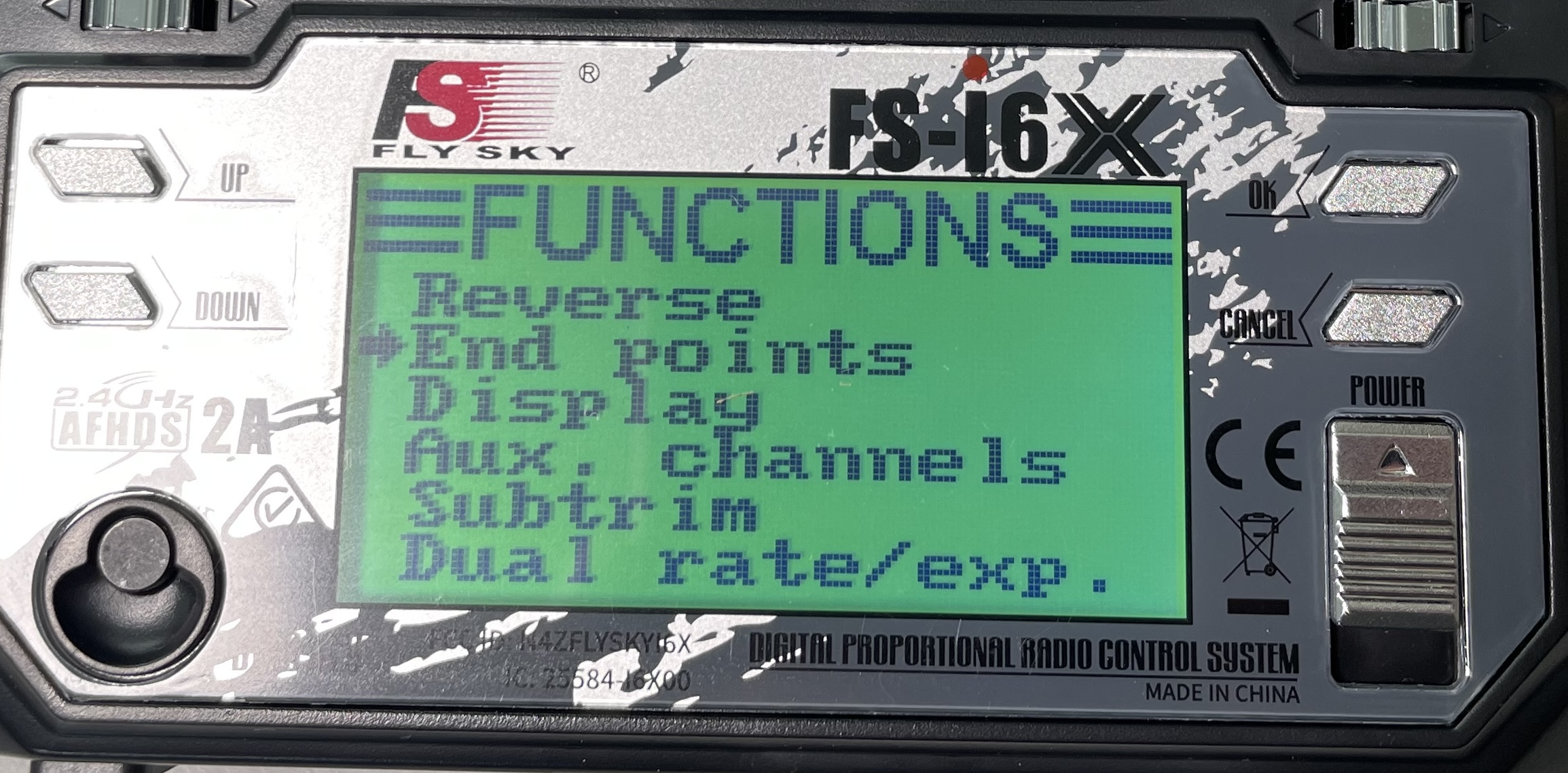
While not essential, it can be helpful to slow down the turning rate. From the main menu, select “Function Setup”:
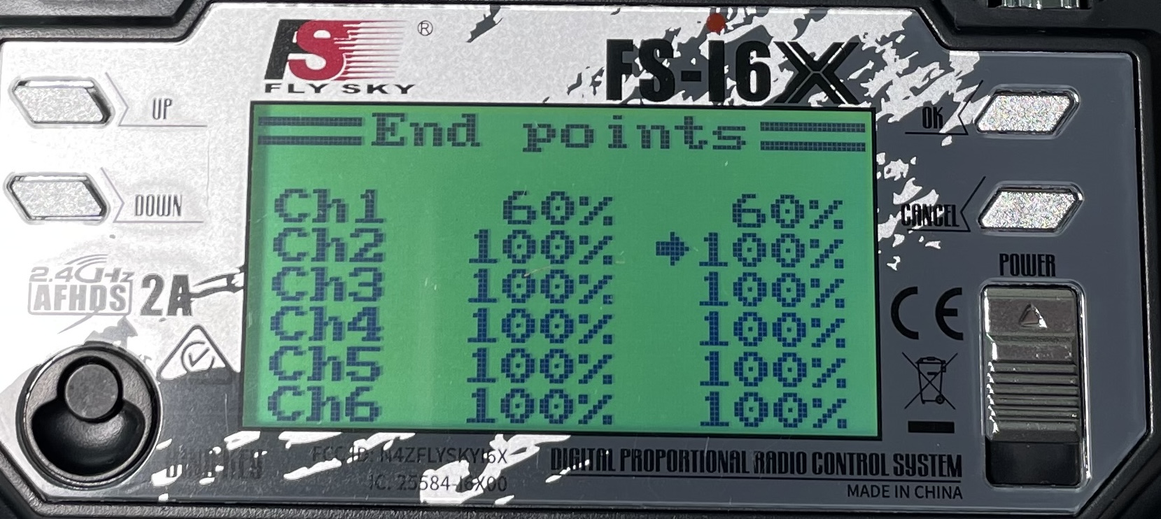
Then select “End Points” and press OK:
Changing the endpoints of CH1 to ~60% in each direction will slow the turning rate down and make the robot more driveable. If you want to slow the whole robot down, you can also reduce the range of CH2:
9. Test Drive
Test your robot away from people. Turn on the radio first, then the robot. The left joystick controls the weapon - move the throttle up to spin the weapon faster. The right joystick is used for driving the robot.
You may find that you need to calibrate the dual motor controller - if that is the case, follow the motor controller directions from the manufacturer.